Removal and installation
To turn the crankshaft of the engine, use a socket wrench or a swivel head, dressed on the head of the damper mounting bolt. Rotate the shaft only in the direction of travel.
Disconnect the wire from the battery. For safety, disconnect the two wires and secure.
Remove the distributor cap, connecting wires and vacuum regulator hose.
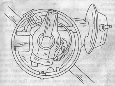
Rotate the crankshaft to TDC on the number one cylinder. Check the alignment of the marks on the rotor and the distributor housing, as shown in fig. 157.

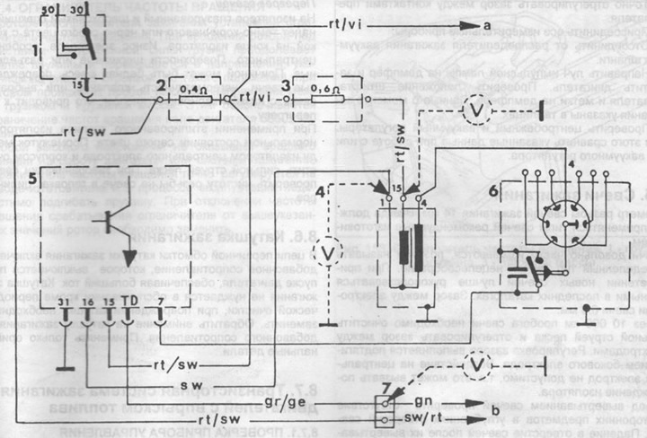
Pic. 156. Diagram of a transistorized ignition system with unified control devices.
1 - ignition switch,
2 - additional resistance 0.4 Ohm,
3 - additional resistance 0.6 Ohm,
4 - ignition coil,
5 - unified control device,
6 - ignition distributor,
a - to the terminal,
c - to the central plug connector,
7 - connecting panel with a terminal for checking the TD.

Pic. 157. Labels on the rotor and ignition distributor housing.
Check the alignment of the pin on the cover of the camshaft drive and the mark "0" on damper.
Loosen the hexagon socket screw on the ignition distributor.
Remove the ignition distributor.
The ignition distributor is installed in the reverse order. If the shaft was rotated during removal and installation, it is necessary to set the TDC of the piston of the first cylinder again. When installing the ignition distributor, align the marks on the rotor and distributor housing. After installing the distributor, adjust the ignition timing as described in section 8.4.
Breaker contact adjustment
Check the condition of the breaker contacts. Replace faulty contacts.
Using a feeler gauge, adjust the gap between the breaker contacts. The plastic block must be located on the cam lobe of the distributor shaft. Loosen the fastening screw in this position and tighten after adjustment.
Check that the breaker contacts in the closed position are adjacent to each other over the entire surface. Gap between contacts -0.3...0.4 mm. Fine adjustment of the contacts can be made using a closed angle gauge according to the manufacturer's instructions.
Centrifugal and vacuum regulators
To fully test the regulators, special instruments are required. These works are preferably carried out at a service station. The following simple work can be done to rule out possible causes of errors.
Vacuum regulator
Check the tightness of the housing and pipelines. Check for ease of rotation of the breaker plate.
Centrifugal regulator
Check the wear of the weights, springs and axles of the weights. Remove thickened grease or excess grease from the weights, as they can have a detrimental effect on the operation of the mechanism.
