
Principle of operation:
- engine 110.922 - four-stroke engine with forced ignition of the mixture, carburetor;
- the remaining engines are four-stroke positive-ignition engines with electronically controlled fuel injection.
Number of cylinders:
- models 280 - 6
- 350SE/450SE models - 8
Cylinder arrangement:
- models 280 - in a row
- 350 SE/450 SE models - V 8
Working volume:
- 2.8 l engine - 2746 cc
- 3.5 l engine - 3499 cc
- 4.5 l engine - 4520 cc
Cylinder diameter:
- 2.8 l - 86.00 mm
- 3.5 l and 4.5 l - 92.00 mm
Stroke:
- 2.8 l - 78.80 mm
- 3.5 l - 65.80 mm
- 4.5 l - 85.00 mm
Compression ratio:
- 2.8 l - 9.0:1
- 3.5 l - 9.5:1
- 4.5 l - 8.8:1
Max Power:
- 280 S - 118 kW (160 hp) at 5500 rpm
- 280 SE - 125 kW (170 hp) at 6000 rpm
- 350 SE - 147 kW (200 hp) at 5800 rpm
- 450 SE - 165 kW (225 hp) at 5000 rpm
Max Torque:
- 280 S/280 SE - 226 Nm at 4000 rpm
- 350 SE - 286 Nm at 4000 rpm
- 450 SE - 378 Nm at 3000 rpm
Compression pressure:
- nominal - 10... 12 atm.
- minimum allowable (on the edge of wear) - 8.5 atm.
Crankshaft main bearings:
- 6-cylinder engine - 7 bearings with bimetal liners
- 8-cylinder engine - 5 bearings with bimetal liners
Valve locations:
- 6-cylinder engine - outboard, V-arrangement
- 8-cylinder engine - outboard
Location of camshafts:
- 6-cylinder engine - 2 overhead shafts
- 8-cylinder engine - one overhead shaft per bank of cylinders
Oil cooling
Oil cooler, air cooled
Cooling system: Forced with water pump, bypass thermostat, viscous fan
Oil filter: Full flow with paper element
Air filter: dry type with filter element
Gas distribution mechanism


Engine design

Maximum wear in longitudinal or transverse directions - 0.1 mm
Permissible value of out-of-roundness and taper:
- nominal value — 0...0.013 mm
- at the wear limit - 0.05 mm
Permissible roughness - 0.003... 0.005 mm
Permissible waviness - 50% of the roughness
Places for measuring the diameter - the upper, middle and lower belts in the cylinder
Cylinder block:
New engine block height:
- 280 S/280 SE - 215.85...216.00 mm
- 350 SE/ 450 SE - 244.85...245.00 mm
Permissible block height after repair:
- 280 S/280 SE - 215.65 mm
- 350 SE/ 450 SE - 244.65 mm
Permissible non-flatness of split surfaces:
- in the longitudinal direction - 0.08 mm
- in the transverse direction - 0.05 mm
Non-parallelism of the upper and lower split surfaces, no more than - 0.05 mm
Permissible roughness:
- upper split surface - 0.020 mm
- lower split surface - 0.025 mm
Air pressure for block crimping - 3.0 bar
Crankshaft:
Machining accuracy tolerances:
- permissible out-of-roundness of the main and connecting rod journals - 0.005 mm (wear limit 0.01 mm)
- permissible taper of the main and connecting rod journals - 0.010 mm (wear limit 0.015 mm)
Permissible out-of-roundness of the main journals when attaching the shaft to the outer journals

- Fillet radii on the main and connecting rod journals - 2.5... 3 mm
- Runout radial rear flange of the crankshaft - no more than 0.02 mm
- Axial runout of the rear flange of the crankshaft - no more than 0.012 mm
The hardness of the surface of the main and connecting rod journals:
- nominal - 66-74
- on the border of wear - 77
Permissible unbalance of the crankshaft 15 Gcm
Crankshaft journal diameter 280/280 SE
- nominal - 59.96...59.95 mm
- 1 repair - 59.71... 59.70 mm
- 2 repair - 59.46... 59.45 mm
- 3 repair - 59.21... 59.20 mm
- 4 repair - 58.96... 58.95 mm
The width of the neck for bearings for adjusting the axial clearance:
- nominal - 29.00...29.02 mm
- repair — up to 29.60 mm
Diameter of connecting rod journals of the crankshaft:
- nominal - 47.96...47.95 mm
- 1 repair - 47.71... 47.70 mm
- 2 repair - 47.46... 47.45 mm
- 3 repair - 47.21... 47.20 mm
- 4 repair - 46.96... 46.95 mm
Width of connecting rod journals of the crankshaft:
- nominal 28.00...28.08 mm
- repair up to 28.30 mm
Liners - 280/280 SE:
Wall thickness:
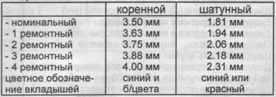
Mounting insert width 280/280 SE
- nominal - 28.78...28.90 mm
- repair 1...4 — 29.40...26.60 mm
Diameter of crankshaft journals 350 SE/450 SE
- nominal - 63.96...63.95 mm
- 1 repair - 63.71... 63.70 mm
- 2 repair - 63.46... 63.45 mm
- 3 repair - 63.21... 63.20 mm
- 4 repair - 62.96... 62.95 mm
The width of the neck for bearings for adjusting the axial clearance:
- nominal - 27.00...27.02 mm
- repair — up to 27.50 mm
Diameter of connecting rod journals of the crankshaft:
- nominal - 51.96...51.95 mm
- 1 repair — 51.71...51.70 mm
- 2 repair - 51.46... 51.45 mm
- 3 repair - 51.21... 51.20 mm
- 4 repair - 50.96... 50.95 mm
Width of connecting rod journals of the crankshaft:
- nominal — 50...50.10 mm
- repair — up to 50.3 mm
Liners - 350 SE/450 SE:
Wall thickness:
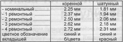
Mounting insert width 350 SE/450 SE
- nominal - 26.80...26.90 mm
- repair 1...4 - 27.60 mm
Radial clearance in bearings:
- main bearings - all engines 0.035...0.075 mm,
- average value - 0.055 mm
- connecting rod bearings (280/280 SE) — 0.015...0.050 mm
- connecting rod bearings (350 SE/450 SE) — 0.035...0.065 mm
- average value - 0.050 mm
- wear limit — 0.08 mm
Axial clearance in bearings:
- main bearings - all engines 0.10...0.24 mm
- connecting rod bearings (280/280 SE) — 0.11...0.23 mm
- connecting rod bearings (350 SE/450 SE) — 0.22...0.38 mm
- wear limit - main bearing - 0.30 mm
- wear limit - connecting rod bearing - 0.50 mm
Connecting rod bolts:
- Thread - M10x1
- The diameter of the thinned part is 8.0 mm
Piston:
Piston diameter - 280/280 SE
- nominal — 86.00...85.98 mm
- 1 repair - 86.50.. 86.48 mm
- 2 repair — 87.00...86.98 mm
Clearance piston - cylinder:
- nominal — 0.02...0.03 mm
- wear limit — 0.08 mm
Piston head recess diameter - not manufactured
Permissible deviations in the mass of a set of pistons in one engine - 4 g, during repair 10 g
connecting rods
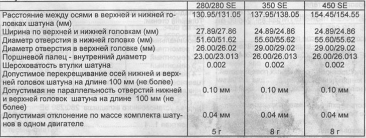
Piston diameter - 350SE/450SE
- nominal — 92.00...91.98 mm
- 1 repair - 92.50... 92.48 mm
- 2 repair — 93.00...92.98 mm
Clearance piston - cylinder:
- nominal — 0.02...0.03 mm
- wear limit — 0.08 mm
Piston head recess diameter:
- 350SE - 52.0mm
- 450 SE - 66.0 mm
Permissible deviations in the mass of a set of pistons in one engine - 4 g, during repair 10 g
Piston pin diameter:
- 280/280 SE - 23.000...22.996 mm
- 350SE/450SE - 26.000...25.995 mm
clearance between piston pin and
- connecting rod head - 0.007... 0.018 mm
- hole in the piston - 0.002... 0.012 mm
Piston ring gaps:
Top ring:
- 280/280 SE/350 SE — 0.30...0.45 mm
- 450 SE - 0.35...0.45 mm
- the maximum allowable gap is 1.0 mm
Middle ring:
- 280/280 SE - 0.30...0.45 mm
- 350SE/450SE - 0.35...0.55 mm
- the maximum allowable gap is 0.8 mm
Lower piston ring - all engines - 0.25.0.40 mm
the maximum allowable gap is 0.8 mm
Height clearances between piston grooves and rings:
Top ring:
- 280/280 SE - 0.050...0.082 mm
- 350 SE - 0.050...0.082 mm
- 450 SE - 0.060...0.090 mm
- the maximum allowable gap is 0.15 mm
Middle ring:
- 280/280 SE - 0.030...0.062 mm
- 350SE/450SE - 0.040...0.070 mm
- the maximum allowable gap is 0.10 mm (280), 0.08 mm (350/450)
lower piston ring
- 280/280 SE - 0.010...0.042 mm
- 350SE/450SE - 0.010...0.042 mm
- the maximum allowable gap is 0.10 mm (280), 0.08 mm (350/450)
Flywheel:
Size "A" (pic. 77)
- 280/280 SE - 19.4 +0.1 mm
- 350SE/450SE - 3.8...3.9 mm
Size "V" (pic. 77)
- in the new engine - 18.5 mm (280/280 SE), 27.4...27.5 mm (V8)
- during repair - up to 17.5 mm (280/280 SE), 26.4 mm (V8)
Permissible lateral runout - 0.05 mm
When processing, be sure to maintain the size "A". Surface of bearing surface of clutch disc "A". Cylinder head:
The total height of the cylinders - 280/280 SE - 93.9... 94.0 mm
Minimum Working Height - 280/280 SE 93.10 mm
Depth - control dimension of the combustion chamber
- 350 SE - 15.85...16.15 mm
- 450 SE - 17.85...18.15 mm
The minimum allowable depth after processing is 15.35 mm (350), 17.35 mm (450)
The maximum allowable non-flatness of the split surface:
- in the longitudinal direction - 0.08 mm
- in the transverse direction - 0.00 mm
Permissible non-parallelism of the upper split surface relative to the lower split surface in the longitudinal direction - 0.10 mm
Permissible surface roughness - 0.06... 0.014 mm
Air pressure during pressure testing of the cylinder head - 2.0 bar
The upper and lower split surfaces of 6-cylinder engines can be machined to a depth of no more than 0.4 mm. When repairing, it is desirable to process both surfaces at the same time.
Valve seat repair
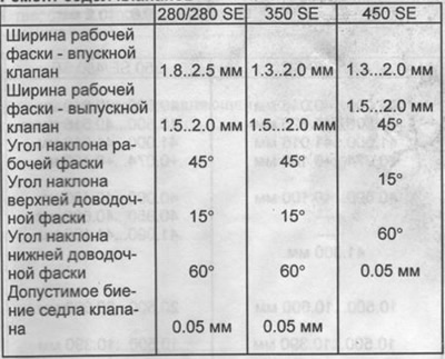
Distance between the split surface of the cylinder head and the valve edge - only for 280
- new intake valve - 3.3 mm
- new exhaust valve - 0.6 mm
After processing:
- intake - 4.20 mm
- outlet - 1.50 mm
The specified dimensions are reduced when machining the split surfaces of the cylinder head. In V-8 engines, these dimensions do not change.
Camshaft:
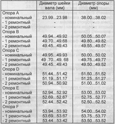
Axial clearance in the camshaft bearings
- a = 0.06 - 0.12 mm
- c = 0.10 - 0.14 mm
- c = 0.05 - 0.09 mm
- d, e, f = 0.06 - 0.10 mm
Axial clearance in supports 0.17 - 0.44 mm
support bushing "A"
- outer diameter 37.95 - 37.93 mm
- inner diameter 24.00 - 24.01 mm
Note: For repair camshafts, repair camshaft housings are used. The camshaft journals are not heat treated. support "A" do not process, put a sleeve or spacer.
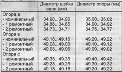
Camshaft and bearing dimensions of the eight-cylinder engine
lower piston ring
- 280/280 SE - 0.010...0.042 mm
- 350SE/450SE - 0.010...0.042 mm
- the maximum allowable gap is 0.10 mm (280), 0.08 mm (350/450)
Flywheel:
Size "A" (pic. 77)
- 280/280 SE - 19.4 + 0.1 mm
- 350SE/450SE - 3.8...3.9 mm
Size "V" (pic. 77)
- in the new engine - 18.5 mm (280/280 SE), 27.4...27.5 mm (V8)
- during repair - up to 17.5 mm (280/280 SE), 26.4 mm (V8)
Permissible lateral runout - 0.05 mm
When processing, be sure to maintain the size "A". Surface of bearing surface of clutch disc "A".
Cylinder head:
The total height of the cylinders - 280/280 SE - 93.9... 94.0 mm
Minimum allowable working height - 280/280 SE - 93.10 mm
Depth - control dimension of the combustion chamber
- 350 SE - 15.85...16.15 mm
- 450 SE - 17.85..18.15 mm
The minimum allowable depth after processing is 15.35 mm (350), 17.35 mm (450)
The maximum allowable non-flatness of the split surface:
- in the longitudinal direction - 0.08 mm
- in the transverse direction - 0.00 mm
Permissible non-parallelism of the upper split surface relative to the lower split surface in the longitudinal direction - 0.10 mm
Permissible surface roughness - 0.06... 0.014 mm
Air pressure during pressure testing of the cylinder head - 2.0 bar
The upper and lower split surfaces of 6-cylinder engines can be machined to a depth of no more than 0.4 mm. When repairing, it is desirable to process both surfaces at the same time.
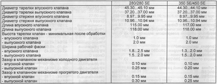
Valves
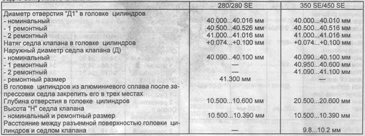
Inlet valve seat
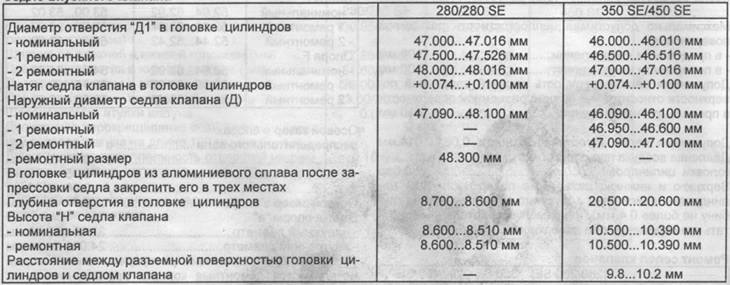
Exhaust valve seat
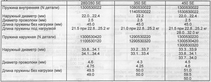
Valve springs
Valve guides and cylinder head bores - all engines
Inlet valve guides:
Outside diameter
- nominal (gray /green/grey/grey-brown) - 14.05-14.03 mm
- 1 repair (marked with red paint) - 14.23-14.21 mm
- 2 repair (white paint mark) - 14.43-14.41 mm
Inner diameter — 9.000 - 9.015 mm
Guide length - 51.5 mm (280), 47.5 mm (350/450)
Holes in the cylinder head:
- nominal (gray /green/grey/grey-brown) — 15.05 - 15.03 mm
- 1 repair (marked with red paint) - 15.23-15.21 mm
- 2 repair (white paint mark) - 15.43 -15.41 mm
Inner diameter - 11.000 - 11.185 mm
Guide length - 54.0 mm (280), 49.0 mm (350/450)
Hole in the cylinder head:
- nominal - 15.02 -15.04 mm
- 1 repair - 15.20 -15.22 mm
- 2 repair - 15.40 -15.42 mm
The amount of preload guide in the cylinder head - + 0.01... + 0.03 mm
