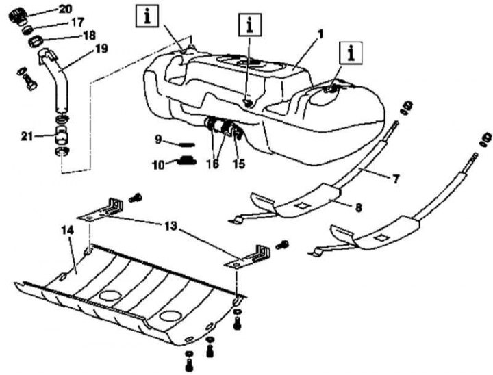
Fuel tank installation details (all models) (1 of 4)
1 - Fuel tank; 7 - Mounting tapes; 8 - Insulating gaskets; 9, 17 - O-rings; 10 - Drain plug; 13 - Protective screen mounting brackets; 14 - Protective screen; 15 - Fuel pump; 16 - Clamps for fastening the fuel pump; 18 - Protective clutch; 19 - Filler neck; 20 - Cover; 21 - Connecting pipe

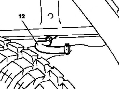
Fuel tank installation details (all models) (2 of 4)
12 - Left ventilation hose

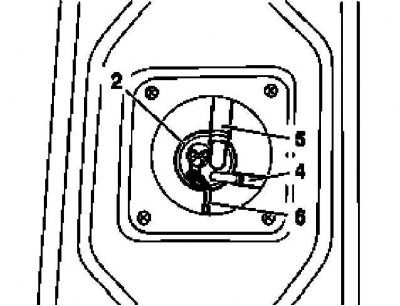
Fuel tank installation details (all models) (3 of 4)
2 - Fuel gauge
4 - Suction fuel line
5 - Ventilation hose
6 - Wiring connectors

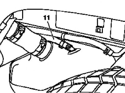
Fuel tank installation details (all models) (4 out of 4)
11 - Right ventilation hose
1. On models of the corresponding configuration (code ET2) activate the service mode of the TELE AID emergency call system (see Section Activation / deactivation of the service mode of the TELE AID emergency call system).
2. Disconnect the negative cable from the battery.
3. Jack up the car and put it on stands.
4. Empty the fuel tank (see Section Emptying the fuel tank).
5. Remove the cover (20) filler neck (19).
6. Remove the left and right rear wheel arch protection panels.
7. Loosen the fixing clamps and disconnect the landing pipe (21) filler neck (19) from the fuel tank.
8. Disconnect from the fuel tank left (12) and right (11) ventilation hoses, - plug the landing fittings.
9. Disconnect the fuel return line from the tank - plug the fitting.
10. Disconnect the communication lines from the fuel gauge (see Section Removal and installation of the gauge of a stock of fuel).
11. Remove the fuel pump (see Section Removal and installation of the fuel pump).
12. Release mounting tapes (7) and remove the fuel tank (1).
13. Installation is carried out in the reverse order.
14. In conclusion (with appropriate equipment) deactivate the service mode of the TELE AID system (see Section Activation / deactivation of the service mode of the TELE AID emergency call system) and clear the memory of the processor of the on-board self-diagnosis system (see chapter Engine Electrical Systems).
